Truth in Balancing
Some suppliers are not providing complete information, "Tool is balanced for 30,000 RPM" yes but at what grade? Without both factors Grade and RPM you might as well say "my car can go 100" there is a big difference between MPH and KPH. Without grade or point of reference to compare it does not mean anything.
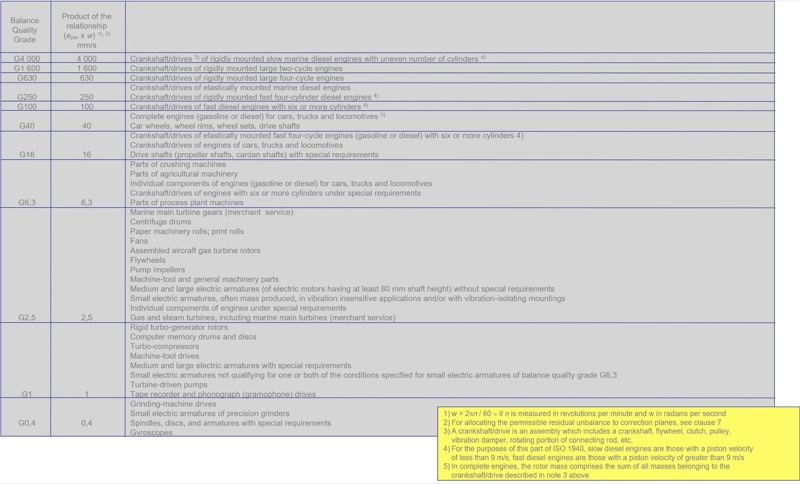
The truth is you want to take as much imbalance out of the holder as you can cost effectively so when you compensate for the cutting tool you have less to adjust or remove. Most machine companies will recommend pre-balanced tool holders in the G6.3 @ max spindle rpm, then when the cutter is added the compensation is just for the cutting tool itself.
When you are looking at assemblies with parts, collet chuck with collet nut, collet, preset screw, cutting tool, it is impossible for the tool holder manufacturer to balance this assembly. We do not know what size, length or weight of the cutting tool. All Tool Holder manufacturer's do the same thing, balance the body of the chuck and hope for the best. We at Pioneer balance the locking nut as well but we still do not know which collet you are going to use or cutter spec's. Again we are working in grams so weight shift is very easy when you add carbide to the nose of any holder.
The largest re-seller of balancing machines in North America says on the tool holders they sell
"Chuck body fine balanced G2.5 at 25.000 rpm or U < 1 gmm".
If you have an operation at 20,000 rpm in your BT30 machine with the BT30 ER16 chuck above, the best the balancing machine can do is G2.5 @ 12,000 rpm to achieve 1 gmm of displacement. It is physically impossible to balance any finer with a tool holder balancing machine. Any manufacturer of tool holders stating the tools are balanced for a finer balance cannot maintain that balance. Another way of saying this is if you check the balance 3 times you will get 3 different answers. The assembly is to light to measure properly and guarantee. Adding the cutter weight to the assembly will make it easier for the balancing machine to sense the tool and balance for higher operating speeds.
A west coast American machine builder that starts with an H updated their balance requirements in 2015 to recommend G2.5 balance grade for speeds over 10,000 RPM's on BT30, BT40 & CAT40, 7,000 RPM's on CAT50. They designate "tooling" not "tool holder". To meet this requirement the assembly must be balanced to G2.5 at operating speed not the tool holder alone.
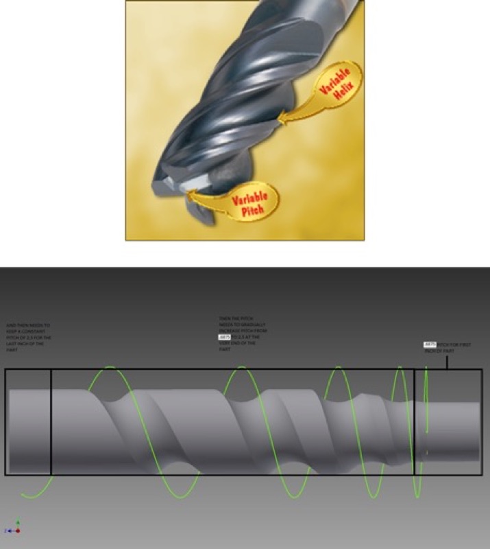
To maintain balance the tool must be re-balanced on every tool change because cutting tools are not balanced. Variable pitch and helix cutting tools are designed to be out of balance on purpose to reduce harmonics. Remember we are discussing grams of weight, it does not take much to take a tool out of balance.
The Variable Factor
Most high performance tooling today is based on a variable pitch, variable helix design. Basically the flute of the cutter are all different thickness and depth on purpose. Unequal flutes provide reduced harmonics. In other words, these cutters are designed out of balance on purpose. Because of this built in unbalance, if you require your tooling to be balanced every tool must be rebalanced at every tool change. The cutter design is forcing this. The orientation of these cutters are not forced so even if you are using the same brand and part number the cutting tool center of gravity is shifting on every tool. Even if you can pre-balance a tool holder and have it repeat, variable cutters negate this work forcing re-balance on every tool change.
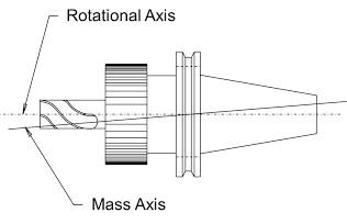
Unbalance is a condition that exists when the Mass Axis of a rotor does not coincide with the Rotational Axis.
- Flaws in the base material
- Voids, seams, and porosity
- All result in unbalance and structural weakness
- Tolerances during fabrication of Tool Holders & Cutters
- Standard Production Tolerances of Drive Slots, Preset Screw Holes, Coolant Ports, & DIN AD/B Flange Ports
- Out of roundness from turning or heat treat
- Improper placement of through holes
- Any machining performed on the tool holder that diminishes the absolute concentricity about the rotational axis contributes to unbalance
- Asymmetrical tool holder design
- Improper balance practice (Mass Symmetry / Par Symmetry)
- Unbalanced Cutting Tools
- Axial movement of preset screws and cutting tools
- Unbalanced Components of the Tool Holder
What Causes Unbalance?
Unbalance Effect
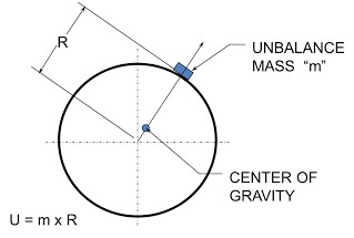
The result of the conditions listed above create a new center of gravity in the tool holder. This center of gravity can be corrected by adding or removing material from the assembly. To make this correction you need to know the following:
- W = Weight of the Assembly
- G = Required “G” rating
- RPM = The operating speed for this assembly
Applied with a 9549 constant you use the following formula to calculate your allowable unbalance.
(U = G x 9549 x W) / RPM
Calculation of “G” 2.5 for a #40 Taper Tool Holder Assembly with a weight of 2.75 lbs at 8,000 and 20,000 rpm a general expression for G 2.5 works out to the following:
(U = 2.5 x 9549 x 2.75) / RPM
Solving these expressions for 8,000 rpm and 20,000 rpm range shows:
- Unbalance for G 2.5 at 8,000 rpm gives an allowable unbalance of 8.2 g.mm
- Unbalance for G 2.5 at 20,000 rpm gives an allowable unbalance of 3.3 g.mm
This shows that as spindle speeds increase the tolerance for allowable unbalance decreases.
Indexable Tooling
Balancing many indexable cutters need to be re-checked at tool index. Most insert IC's are only held within 0.002", the corner radius, etc... when you are trying to keep tooling balanced within grams for G2.5 @ X, the weight shift from the insert tolerance and the change from indexing will take your assembly out of balance depending on the RPM.
There is 2 different types of balancing:
- Static: also know as production balance is when you calculate the imbalance of the holder pre-production to make the holder a symmetrical design. This is also known as engineered balance.
- Dynamic: is when you use a machine to physically spin the holder to measure the imbalance and correct by adding or removing material.
Some manufacturer’s believe a symmetrical design will provide sufficient balance correction. In today’s market with spindle speeds at 15,000 RPM’s and higher, Dynamic Balance is required on all tool holders and components to reduce machine tool wear and improve cutting tool performance. Engineer balancing, if done correctly, can only provide balance for 5,000 RPM or less. Consider that most tool holders a have coolant holes through the center. Engineered balance assumes the drilled hole is straight, I am sorry but every drill wanders depending on depth and these differences cannot be compensated for in static or engineer balance.
2 different types of Dynamic Balancing Machines:
- Hard Bearing Balancing Machines: Tool Holder Balancing Machines are Hard Bearing, the spindle sits in bearings and the sensor measure the difference in displacement. The tool holder is measured, indexed 180 degrees and then measuring again. The difference in readings in the imbalance, correction is made and the process is repeated to verify. These machines have a sensitivity down to +/- 0.25 g.mm or 0.50 g.mm total. Depending on tool weight, these machines can balance and repeat G2.5 @ 30,000 RPM.
- Soft Bearing Balancing Machines: Soft Bearing employs a tray hanging from music wires. The tool holder mounted in an arbor is rotated in the tray, the imbalance creates movement on the music wires which is measured. Soft Bearing Balancing is the most sensitive and G0.4 @ any RPM can be achieved on these machines. Due to the cost of this type of balancing it is not longer used for tool holders.